In the previous parts of the series we talk about VMM basics and VMXON operation. If you are not able to do a successful VMXON (VMX root operation) then you may have missed setting up few bits. To summarize, here are the checks that processor perform before entering vmxon.
- Check VMX support in processor using CPUID.
- Determine the VMX capabilities supported by the processor through the VMX capability MSRs.
- Create a VMXON region in non-pageable memory of a size specified by
IA32_VMX_BASICMSR(or just 4KB page) and aligned to a 4-KByte boundary. - Initialize the version identifier in the VMXON region (the first 31 bits) with the VMCS revision identifier reported by capability MSRs.
- Ensure the current processor operating mode meets the required CR0 fixed bits (CR0.PE = 1,* CR0.PG* = 1).
Other required CR0 fixed bits can be detected through theIA32_VMX_CR0_FIXED0andIA32_VMX_CR0_FIXED1MSRs. - Enable VMX operation by setting CR4.VMXE = 1. Ensure the resultant CR4 value supports all the CR4 fixed bits
reported in theIA32_VMX_CR4_FIXED0andIA32_VMX_CR4_FIXED1MSRs. - Ensure that the
IA32_FEATURE_CONTROLMSR (MSR index 3AH) has been properly programmed and that its lock bit is set (Bit 0 = 1). - Execute VMXON with the physical address of the VMXON region as the operand. Check successful execution of VMXON by checking if RFLAGS.CF = 0.
If you have properly follow these steps then you must get VMXON successfully.
Setting up VMCS (VM Control Structures)
Major hypervisor development consist of setting up VMCS structure properly. VMCS (Virtual machine control structures) is a structure in memory that our processor uses to store and keep track of data requires during VMX transition i.e during switching from VM non root to VM root operation and vise versa. Things like - guest eip while getting inside VMX non root operation(running guest os), host eip when returning from VMX non root operation, Instruction that will cause VMEXIT etc are saved in VMCS structure.
You can create a VMCS for a VM by allocating a region in memory(known as VMCS region). This memory should be 4kb aligned and zeroed out just like VMXON region. Before allocating the memory lets first discuss properties of VMCS region.
Properties of VMCS structure:
- A VMM can use a different VMCS for each virtual machine that it supports. For a virtual machine with multiple logical processors (virtual processors), the VMM can use a different VMCS for each virtual processor.
- A processor can have many VMCS( for multiple VMs) that they define as active. But will only have one VMCS that it use/execute at a given time called current VMCS.
- All VMCS related operations can be done by using
VMREADandVMWRITEinstruction.
Different states of VMCS:
Lets look at the below figure:
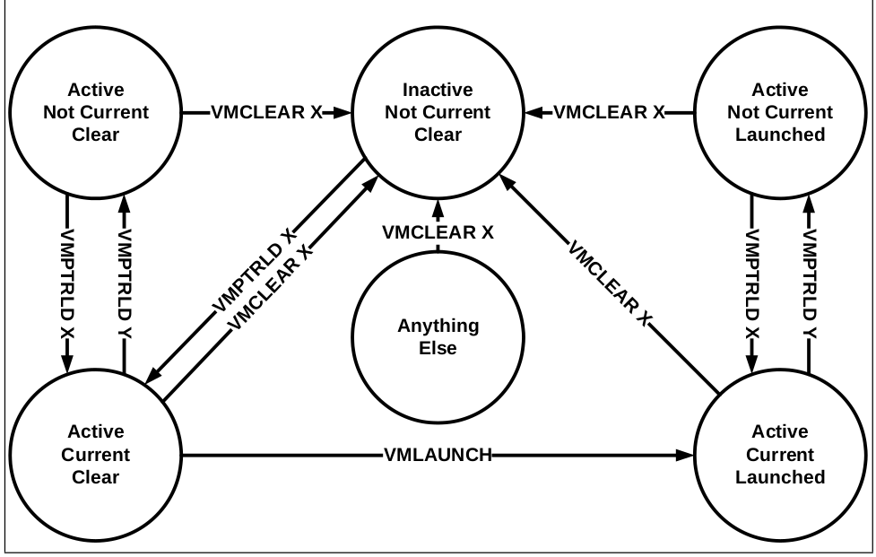
We have already talked about Active and Current states of VMCS. What remain is Launched state, which determine if that VMCS is launched previously or not. To launch a state we use VMLAUNCH , once the state is launched then we need to do VMRESUME on that state to launch it again.
Note:-Launching just means stating the VM or getting inside VM Non-root operation for that VMCS.
Lets see operations that you can use on VMCS:-
VMPTRLD - Will make the VMCS Active and current.
VMCLEAR - Change the state from current to Not current. Idealy should be used before every VMPTLDR so that any previous current VMCS become Non current.
VMLAUNCH - To launch the VMCS or VM defined by VMCS.
VMRESUME - Used to launch again the previously launched VMCS. Used to launch the VM which is exit (VMEXIT) due to some reason.
The above figure can be easily understood by keeping in mind these terms.
Before moving further with theoretical aspects of VMCS, lets first allocate 4Kib region for that and zero it out.
// CH 23.7, Vol 3
// Enter in VMX mode
MYPAGE_SIZE = 4096;
uint64_t *vmcsRegion = NULL;
...
bool allocVmcsRegion(void) {
	vmcsRegion = kzalloc(MYPAGE_SIZE,GFP_KERNEL);
   	if(vmcsRegion==NULL){
		printk(KERN_INFO "Error allocating vmcs region\n");
      	return false;
   	}
	return true;
}
The format of VMCS region is as follow.
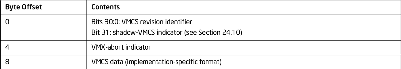
The first 4 bytes of the VMCS region contain the VMCS revision identifier at bits 30:0. So, lets put that in first 4 bytes:
long int vmcsPhyRegion = 0;
	if (allocVmcsRegion()){
		vmcsPhyRegion = __pa(vmcsRegion);
		*(uint32_t *)vmcsRegion = vmcs_revision_id();
	}
	else {
		return false;
	}
The next 4 bytes are abort indicator. A logical processor writes a non-zero value into these bits if a VMX abort occurs. We are not required to write anything on these bytes.
The remainder of the VMCS region is used for VMCS data (those parts of the VMCS that control VMX non-root operation and the VMX transitions). Setting this structure is our biggest task to make hypervisor run successfully. You can only change VMCS Data if the VMCS is current and Active VMCS. So, lets first make our vmcs current using VMPTRLD. VMPTRLD takes address of VMCS structure as the operand.
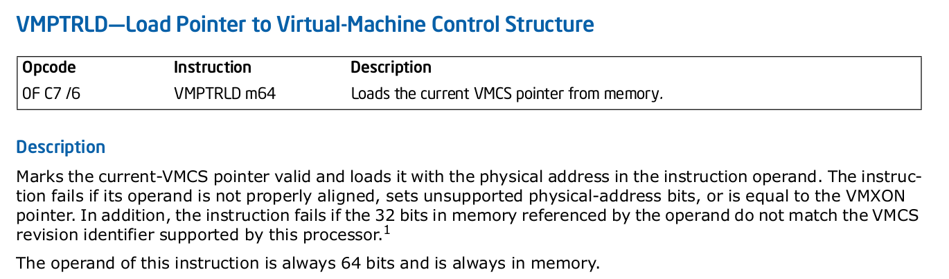
Lets do the same in our code.( We have used setna to check if the instruction succeeded or not.
static inline int _vmptrld(uint64_t vmcs_pa)
{
	uint8_t ret;

	__asm__ __volatile__ ("vmptrld %[pa]; setna %[ret]"
		: [ret]"=rm"(ret)
		: [pa]"m"(vmcs_pa)
		: "cc", "memory");
	return ret;
}
...
//making the vmcs active and current
	if (_vmptrld(vmcsPhyRegion))
		return false;
	return true;
Now what remains is to initialize the VMCS data structure.
Initializing VMCS data
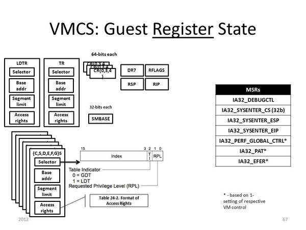
VMCS data is organized in 6 parts:-
- Guest-state area - This space contains information/values of guest state when processor transtion to VM non-root mode. Or in simple terms Registers state of the guest for next VM entry like guest eip, esp, different MSR's value etc.
- Host-state area - This buffer contains processor state that need to be loaded back after the VMexit occur(transition to VM root).
- VM-exit control fields - VM-exit control fields govern the behavior of VM exit. For example, what msr need to be saved on VM-exit etc.
- VM-execution control fields - These fields control processor behavior in VMX non-root operation. They determine in part the causes of VM exits.
- VM-entry control fields - These fields control VM entries or basic operations on VM-entry.For example, what registers and msr to be loaded etc.
- VM-exit information fields - These fields receive information on VM exits and describe the cause and the nature of VM exits. They are used for debugging purposes only and we don't need to initialize them.
We need to setup all the fields except VM-exit information fields. First we are going to setup VM-execution control then remaining once.So, lets start the coding again.
VM-execution control field
VM execution control further divided into following fields
- Pin-based (asynchronous) controls
- Processor-based (synchronous) controls
- Exception bitmap
- I/O bitmap addresses
- Timestamp Counter offset
- CR0/CR4 guest/host masks
- CR3 targets
- MSR Bitmaps
- Extended-Page-Table Pointer (EPTP) (Will ignore for now)
- Virtual-Processor Identifier (VPID) (Will ignore for now)
Let's learn about each of these field and set the one that are required for VM entry. But first you need to knew few terms:
default 0-settings - means those bytes have 0 value set by default
default 1-settings - means those bytes have 1 value set by default
Pin based controls - One 32-bit value that controls asynchronous events in VMX non-root.
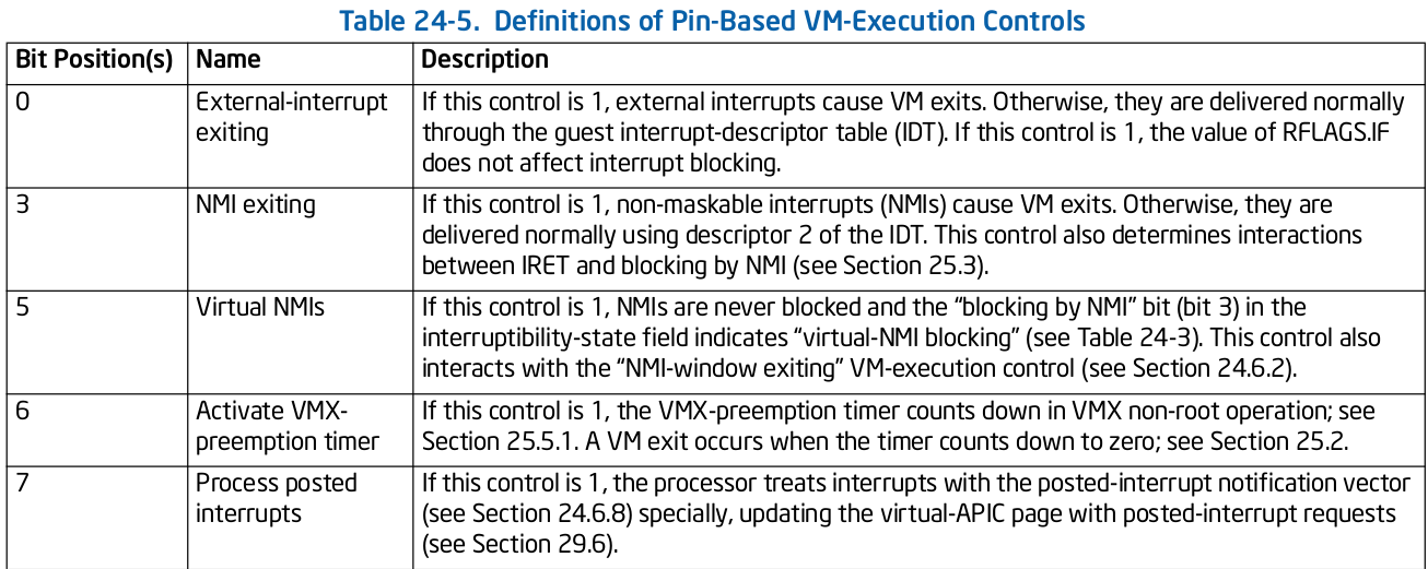
It supports settings governed by IA32_VMX_PINBASED_CTLS MSR. According to Intel document this is how we can set pin based controls.
Above complex wording just means in simple words that we can put IA32_VMX_PINBASED_CTLS values to pin based controls but we need to do and operation between first 32 bits to next 32 bits to get the supported value of that bit in pin based control.
#define MSR_IA32_VMX_PINBASED_CTLS		0x00000481
#define PIN_BASED_VM_EXEC_CONTROLS		0x00004000
...
bool initVmcsControlField(void) {
    uint32_t pinbased_control0 = __rdmsr1(MSR_IA32_VMX_PINBASED_CTLS);
    uint32_t pinbased_control1 = __rdmsr1(MSR_IA32_VMX_PINBASED_CTLS) >> 32;
    uint32_t pinbased_control_final = (pinbased_control0 & pinbased_control1);
	vmwrite(PIN_BASED_VM_EXEC_CONTROLS, pinbased_control_final);
Processor based controls - Controls handling of synchronous events
i.e., events caused by execution of specific instructions. Similar to pin based control we can set proc based control using IA32_VMX_PROCBASED_CTLS.
#define MSR_IA32_VMX_PROCBASED_CTLS		0x00000482
#define PROC_BASED_VM_EXEC_CONTROLS		0x00004002
...
bool initVmcsControlField(void) {
...
    uint32_t procbased_control0 = __rdmsr1(MSR_IA32_VMX_PROCBASED_CTLS);
    uint32_t procbased_control1 = __rdmsr1(MSR_IA32_VMX_PROCBASED_CTLS) >> 32;
    uint32_t procbased_control_final = (procbased_control0 & procbased_control1);
    vmwrite(PROC_BASED_VM_EXEC_CONTROLS, procbased_control_final);
There is also a secondary processor based controls which you can use for further settings of synchronous events setup. You can set it up the same way you are setting processor based controls.
Exception bitmap - This is a 32-bit field in which one bit is for each exception. Setting this will define which exception should cause vmexit. We are just going to set it up to 0 to ignore vmexit for any guest exception.
#define EXCEPTION_BITMAP				0x00004004
...
bool initVmcsControlField(void) {
...
	vmwrite(EXCEPTION_BITMAP, 0);
I/O bitmap - Tells which I/O port request need to cause VMexit. Its two 4K bitmaps (A and B) -
A contains one bit for each I/O port in range 0000h through 7FFFh
B contains one bit for each I/O port in range 8000h through FFFFh
We can ignore this field as it is not mandatory to set.
Timestamp Counter offset - Used to set TSC which we can ignore for now.
CR0/CR4 guest/host masks - Define which bits in CR0/CR4 will cause VMexit. Done through masking. Host/guest mask determines who “owns” that bit (guest or host) in CR0/CR4.
- For bits set to 1 in the mask, these are owned by host
- Guest bit-setting events
- Bits set in the mask that differ from respective shadow value will cause VMExit
- Guest bit-read event for bit in bitmask will read from corresponding shadow register
- For bits set to 0 in the mask, these are owned by guest
We don't care if our guest is accessing CR0/CR4, hence we gone ignore them for now.
CR3-target values - Allows for an exception to the rule of exiting for all MOV to/from CR3. Does not cause a VM exit if its source operand matches one of these values.
We can ignore that to.
MSR Bitmaps - Partitioned into four 1KB contiguous blocks.
- Read bitmap for low MSRs
- Read bitmap for high MSRs
- Write bitmap for low MSRs
- Write bitmap for high MSRs
If the bitmaps are used, an execution of RDMSR or WRMSR causes a VM exit if the value of RCX is in neither of the ranges covered by the bitmaps or if the appropriate bit in the MSR bitmaps (corresponding to the instruction and the RCX value) is 1.
We can happily ignore that for our minimalist hypervisor.:)
Since we are done with VM-execution control fields, now lets setup VM-entry control fields and VM-exit information fields.
VM-exit control fields
VM-exits field consist of two groups:
- VM-Exit Controls
- VM-Exit Controls for MSRs
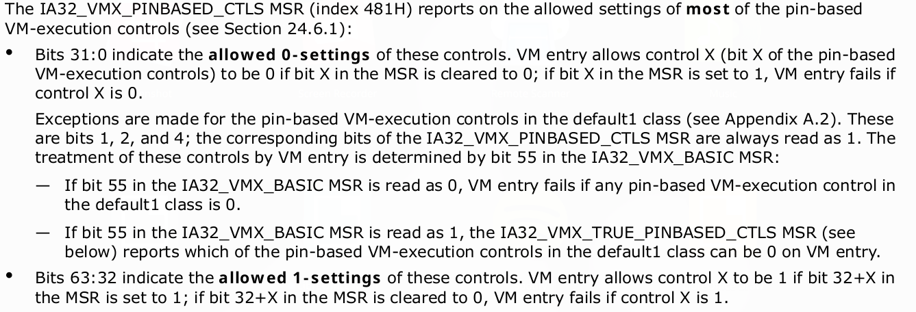
VM-Exits Controls - The VM-exit controls constitute a 32-bit vector that governs the basic operation of VM exits. Below table give details of what each bit corresponds.
VM-Exit Controls for MSRs - A VMM may specify lists of MSRs to be stored and loaded on VM exits. Below fields show how can MSR's be restored on VMExit.
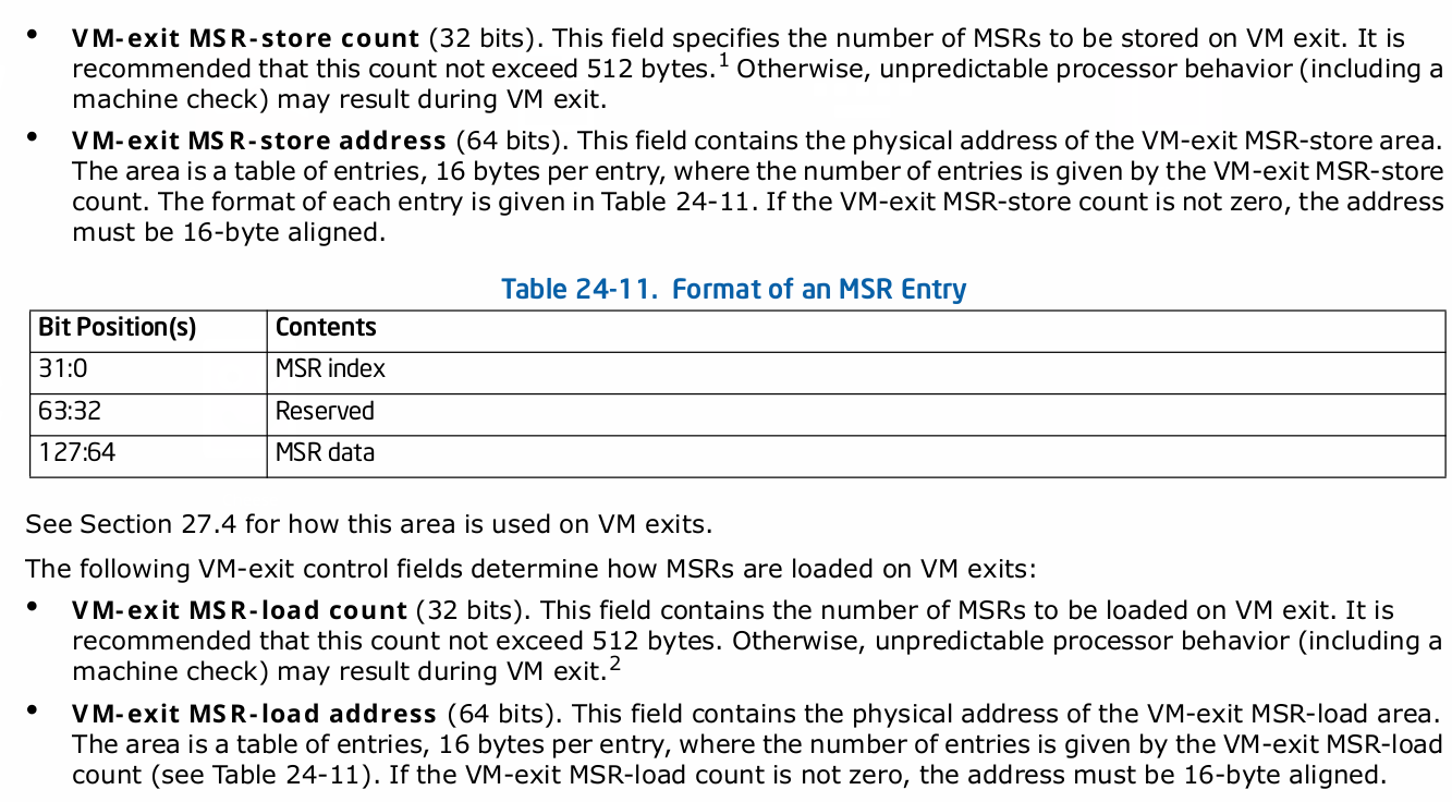
We can skip the VM-Exit controls for MSRs since its optional to use. So, what remain is to set VM-Exit control. VM-Exit control depends on if the VM exit is occur in 64 bit space or not. Hence, we need to set bits 9-Host address space size to 1 and can put the remaining bits from MSR_IA32_VMX_EXIT_CTLS.
#define VM_EXIT_CONTROLS				0x0000400c
#define MSR_IA32_VMX_EXIT_CTLS			0x00000483
#define VM_EXIT_HOST_ADDR_SPACE_SIZE	0x00000200
...
bool initVmcsControlField(void) {
...
    vmwrite(VM_EXIT_CONTROLS, __rdmsr1(MSR_IA32_VMX_EXIT_CTLS) |
            VM_EXIT_HOST_ADDR_SPACE_SIZE);
VM-entry control fields
Its 32-bit vector that controls the basic operation of VM entries. It consists of three groups-
- VM-Entry Controls
- VM-Entry Controls for MSRs
- VM-Entry Controls for Event Injection
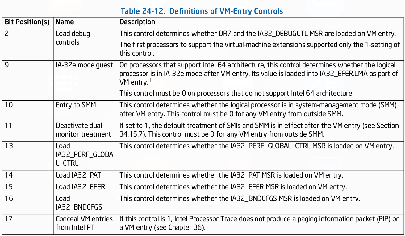
VM-Entry Controls - Used while VM entries.
VM-Entry Controls for MSRs - A VMM may specify a list of MSRs to be loaded on VM entries. The following VM-entry control fields manage this
functionality:
- VM-entry MSR-load count (32 bits)- This field contains the number of MSRs to be loaded on VM entry.
- VM-entry MSR-load address (64 bits)- This field contains the physical address of the VM-entry MSR-load area.
VM-Entry Controls for Event Injection - VMX operation allows injecting interruptions to a guest virtual machine through the use of VM-entry interrupt-information field in VMCS. It generate event on next VMEnter.
Happens after all guest state is loaded.
Allows injection of:-
- External interrupts
- Non-maskable interrupts
- Exceptions (eg Page faults)
- Traps
If the interrupt-information field indicates a valid interrupt, exception or trap event upon the next VM entry; the processor will use the information in the field to vector a virtual interruption through the guest IDT after all guest state and MSRs are loaded.
We will configure the VM-entry in same way we have configured VM-exit.
#define VM_ENTRY_CONTROLS				0x00004012
#define MSR_IA32_VMX_ENTRY_CTLS			0x00000484
#define VM_ENTRY_IA32E_MODE				0x00000200
...
bool initVmcsControlField(void) {
...
    vmwrite(VM_ENTRY_CONTROLS, __rdmsr1(MSR_IA32_VMX_ENTRY_CTLS) |
		VM_ENTRY_IA32E_MODE);
That's it for this part. We will setup Guest state and Host state in next part. You can see the complete code here.